Viewing products
All the products are shown here. Click on any of the categories or sub-categories to see products in that category. To move to a different category UNTICK your original choice and then tick your new choice.Search
If you are searching for a specific part by JRH number, please put just the number into the search box, i.e. "254". Please be aware that some numbers will bring up other fittings too, i.e. "96" will also bring up products of 1/96 scale.Fittings list pictures
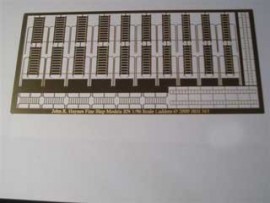
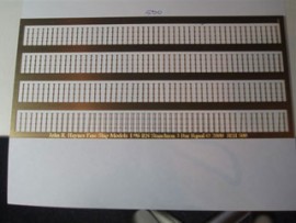
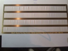
1/192 scale photo-etch

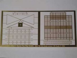
1/200 scale Photo-etch
1/48 scale photo-etch

Atlantis


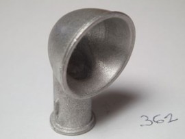
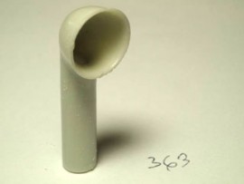
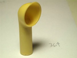
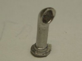
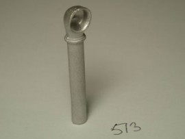
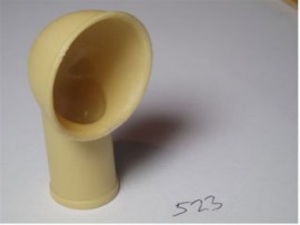
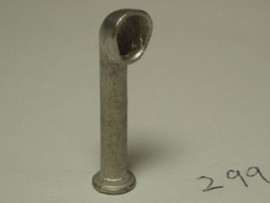
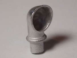
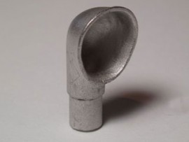
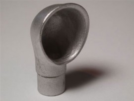
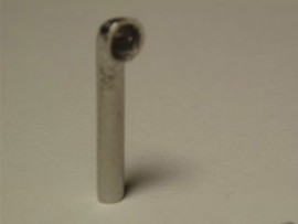
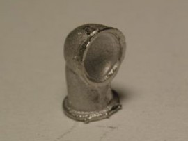
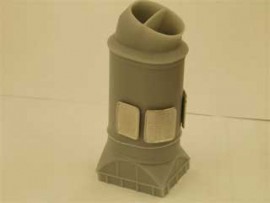
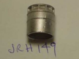
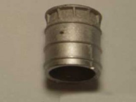
Cowl Vents
DVDs

General Merchant


Merchant Shipping
Royal Navy


Turbinia
Uncategorized
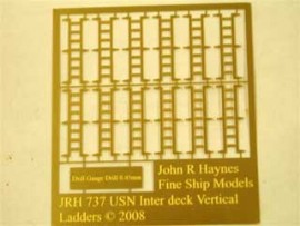
US Navy
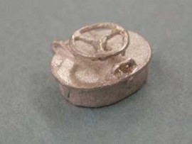


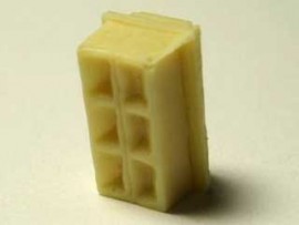
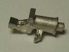
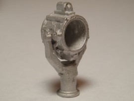
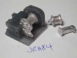
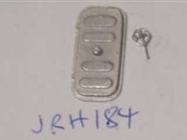
![JRH814 a hand-held bulkhead mounted fire extinguisher at 1/96 scale [ 8mm high ]-image](https://johnrhaynes.com/shop/images/cache/JRH824.270.jpg)


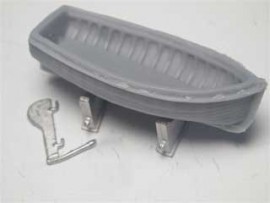
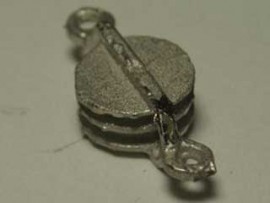
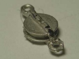
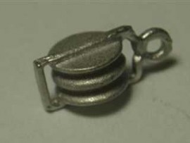
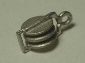
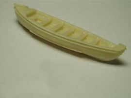
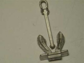
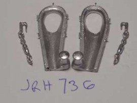
![JRH360 Liberty Davit [ pair]-image](http://johnrhaynes.com/shop/images/cache/JRH360.270.jpg)

1/192 scale photo-etch
1/200 scale Photo-etch
1/48 scale photo-etch
Atlantis
Cowl Vents
DVDs
General Merchant
Merchant Shipping
Royal Navy
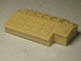
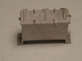
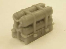
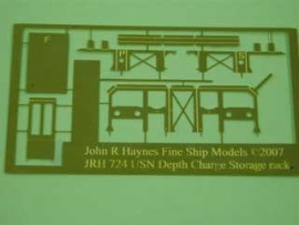
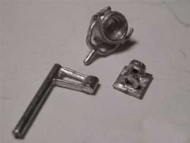
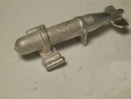
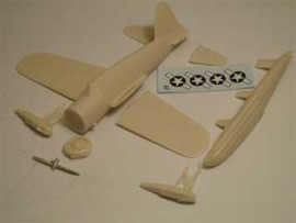
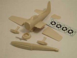
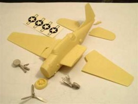
Construction guide(Click on the thumbnail pictures above. Hover the mouse towards the top left or right of the picture when it opens, to move on to the next picture or back to the previous one.)1. Full kit of parts to clean up2. Fit top flange3. Fit 4 rows of bomblets4. Fit rear blast shield and drill out control colunm to fit wire handle as shown and then fit the control column into the shield hole and top flange hole, [wire not supplied].5. and 6. Completed kit.
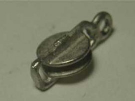
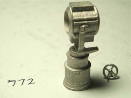
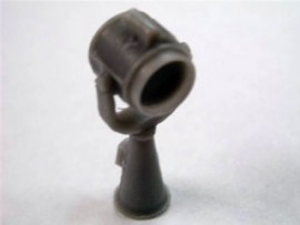
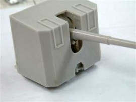
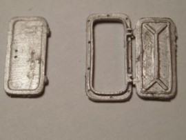
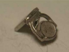
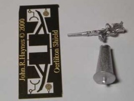
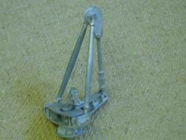
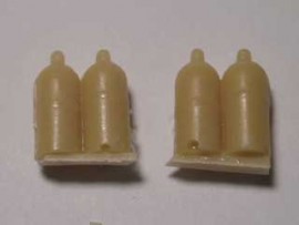
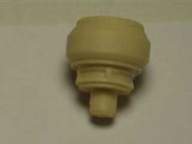
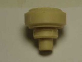
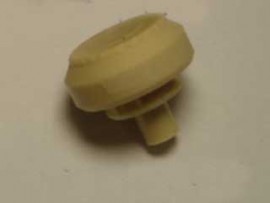
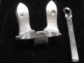
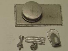
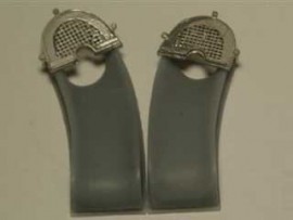
This is a scale 1/96 part.Construction guide:(Click on the thumbnail pictures above. Hover the mouse towards the top left or right of the picture when it opens, to move on to the next picture or back to the previous one.)a) the complete kitb) fix the right-hand bracket where shownc) fix the searchlight bowl in the RH bracket hole and in the LH bracket open slotd) drill and fix the handwheel where shown and after inserting a clear disc [ not supplied ] fix the dome shaped rear piecee) the complete assembly
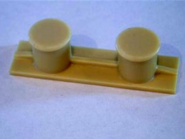
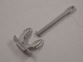
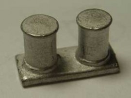
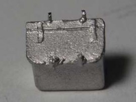
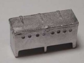
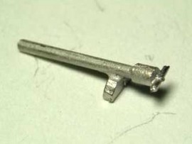
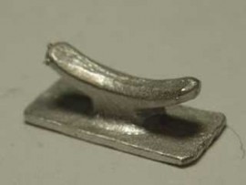
P1 twin bitt/bollard 44mm long x 11mm wide x 11mm high [1 in 48 scale]***This is an END OF LINE item – once these are gone, they are gone!**(The copyright of this item remains with John R Haynes.)
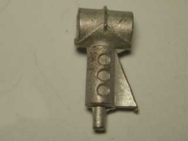
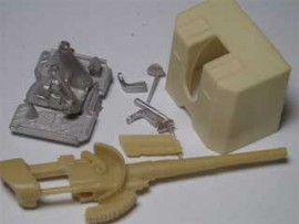
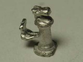
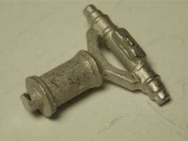
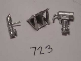
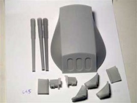
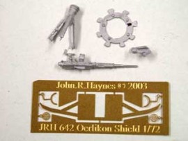
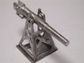
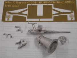
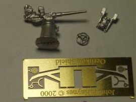
Construction Guide:Cut out the three openings in the shieldAssemble the gun with the w/m base (having a slight angle at the front edge) sliding into the trunnion.Drop the barrel into the top of the trunnion and fix and then fix the sight bar where shown. Lastly drill out the wheel sockets with 0.8mm approx drill and fix the two wheels.Slide the assembled gun into the shield between the trunnion bottom flange and the two angled side supports.
Please note: No shield is included with this kit.Construction Guide:
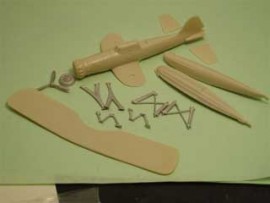
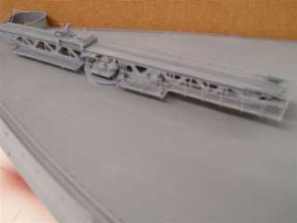
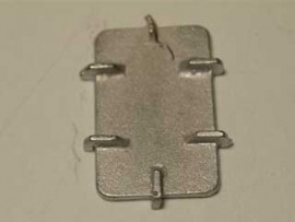
1. Solder/Glue these three sections together - make sure that you get the indicated FFF and RRR.2. Put on the 1and 14 end brackets.3. Start to fix all other internal brackets -make sure 2a slots into 2a position. Spring sides to help assembly.4. Fix 4 x S brackets where indicated.5. Bend up A and B brackets --take care when soldering top of brackets not to intefere with cetntral hole/slot with excess solder/glue.6. Fix A and B to main frame [ this is a tight fit ] and add the 4 multi-hole strip to the brackets to close the gaps.7. Bend up loose tray and fix where shown at the Front RH side. No location provided as this tray is optional.8. Bend up the two brackets that fit onto the underside of A and B brackets. These represent the wheels that travel around the edge of the circular raised central drum on which the toothed annular gear sits centrally.9. This is the start of the two loose/sliding extension pieces, fit one side onto the bottom piece.10. Fix all 5 internal spacers keeping the smallest tab at the bottom. This will allow the assembled piece to slide without fouling.11. Fix the top piece which sits below the top of the side pieces.12. Fix the remaining side to complete and clean up.13. This shows the sliding extension piece in position.14. Aircraft Trolley, fold up as shown.15. Add brackets Z and X.16. Fit to the Catapult the trolley where required with the higher trolley brackets to be secured to the Walrus aircraft [ JRH 603 ] towards the tail end and the lower brackets to be secured under the aircraft lower wing where the fuselage has a step.17. The ring provided sits centrally on the raised circular platform. For more information on this Catapult , obtain a copy of Model Shipwright number 33 dated Sept 1980 ISBN 0 85177 190 4 This article has pictures and lots of other ancilliary information.
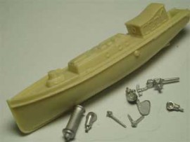
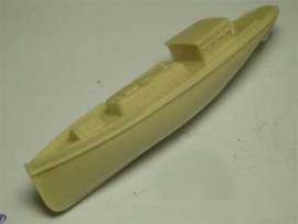
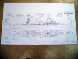
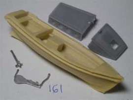
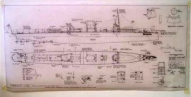
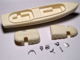
This plan is to go with my 1/96 hull sold by Fleetscale.com and many fittings are in the shop.
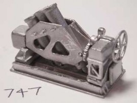
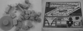
Construction:a: Start of Assembly ------ Fit together the side framesto the base.b: Make sure to fit the pivot re-inforcing tabs when sliding the front panel back at an angle.c: Fold up the top tray and attach to crane base at the top of the left hand side.d: Fit the two top tray supporting brackets.e: Spring fit the two white-metal drums where shown and glue on the resin parts shown in the picture . To get good adhesion lightly run the brass with fine sandpaper before fixing.f: Another view of previous step.g: Fit the back panel. You will need to trim the locating tabs a little to get the back on.h: Fit the other base parts as shown.i: Fit the top tray with the textured floor.j: fit the top tray gear.k: Cut out the Jib parts and when assemblingfix the RH side piece to the top piece which is the shorter of the two [top and bottom].l: Remember that with PE the half-etched line is Bend to Close.m: Bend the bottom piece as shown.n: Drill all 5 pulley assembles [ 2 single/2 double and 1 four pulley ] with 1mm drill all the way through and the two double ones shown are fittedas shown.o: The central 4 pulley assembly must be fitted by drilling a new 1mm hole at the bottom of the side frame where shown and not at the existing hole.p: The final product.
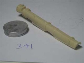
Construction guide(Click on the thumbnail pictures above. Hover the mouse towards the top left or right of the picture when it opens, to move on to the next picture or back to the previous one.)1. The complete kit of parts.2. Drill out and bend wire as shown [ wire not supplied ]3. Fix this part where shown after drilling out the trunnion 4. Drill out and fix the elevating wheel andboth platforms5. Fix in place the sight assembly6. Fix on the barrel7. The completed gun RH8. The completed gun LH
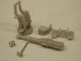
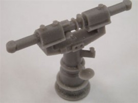
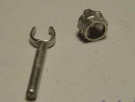
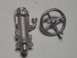
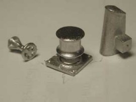
Construction guide:(Click on the thumbnail pictures above. Hover the mouse towards the top left or right of the picture when it opens, to move on to the next picture or back to the previous one.)1: There are 6 parts in the kit.2: Drill the baseframe 0.5mm drill to take seats and trunnion wire handles.3: Clean off the two front pads and rear pad of the baseframe to allow trunnion to sit squarely on the baseframe.4: Jiggle the baseframe over the trunnion and glue in position using the three pads.5: Fix the recoil cylinders to the barrel.6 and 7: Glue the barrel assembly into trunnion with tail in chute.8: Bend 28g of copper wire or similar (not provided) to this shape x2, for the handles.9: Fix the handles into the trunnion where shown.
Turbinia
Uncategorized
US Navy
Construction guide(Click on the thumbnail pictures above. Hover the mouse towards the top left or right of the picture when it opens, to move on to the next picture or back to the previous one.)1. Full kit of parts to clean up2. Fit top flange3. Fit 4 rows of bomblets4. Fit rear blast shield and drill out control colunm to fit wire handle as shown and then fit the control column into the shield hole and top flange hole, [wire not supplied].5. and 6. Completed kit.
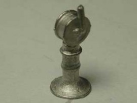
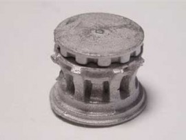
This is a scale 1/96 part.Construction advice:(Click on the thumbnail pictures above. Hover the mouse towards the top left or right of the picture when it opens, to move on to the next picture or back to the previous one.)a) Showing the 9 parts in the kit.b) Fit the circular base into the baseframe keeping the circular base bottom ring rear-facing.c) Note that the 2 mainstruts have a noticable bend to the bottom fixing ring. The top ring has a lesser angled bend.d) Drill the top wheel assembly 1mm and fix the rear shorter strut to this.e) Drill the baseframe 1mm to fix the two main long struts. The hole in the baseframe should be just above and to the rear of the rear pip.f) Fit all the struts and locate the two main strut loops onto the top wheel assembly pips.g) Fit the top plate to the baseframe.h) Fix the seperate wheel assembly to the top plate on the baseframe.i) Seperate wheel for the PE crane JRH 703.j) On completion, the Crane should look like this.
This is a scale 1/96 part.Construction advice:(Click on the thumbnail pictures above. Hover the mouse towards the top left or right of the picture when it opens, to move on to the next picture or back to the previous one.)a) Showing the 9 parts in the kit.b) Fit the circular base into the baseframe keeping the circular base bottom ring rear-facing.c) Note that the 2 mainstruts have a noticable bend to the bottom fixing ring. The top ring has a lesser angled bend.d) Drill the top wheel assembly 1mm and fix the rear shorter strut to this.e) Drill the baseframe 1mm to fix the two main long struts. The hole in the baseframe should be just above and to the rear of the rear pip.f) Fit all the struts and locate the two main strut loops onto the top wheel assembly pips.g) Fit the top plate to the baseframe.h) Fix the seperate wheel assembly to the top plate on the baseframe.i) Seperate wheel for the PE crane JRH 703.j) On completion, the Crane should look like this.
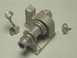
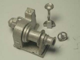
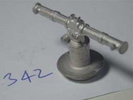
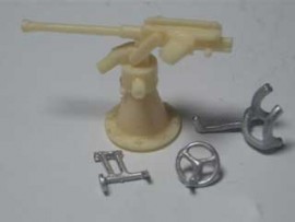
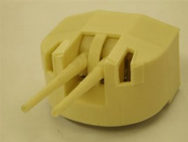
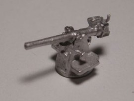
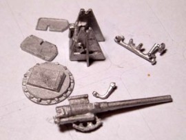
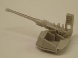
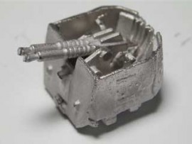
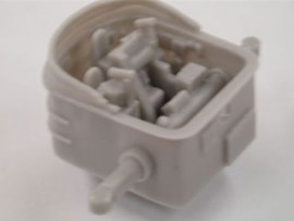
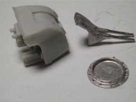
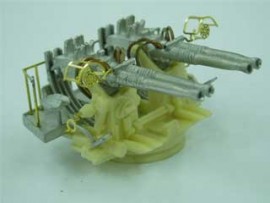
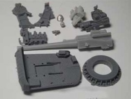
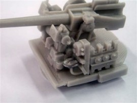
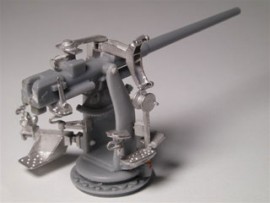
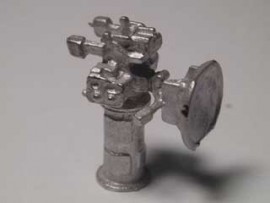
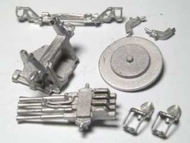
Construction Guide:This is JRH 93 the USN 5"/38 gun assembly guide.(Click on the thumbnail pictures above. Hover the mouse towards the top left or right of the picture when it opens, to move on to the next picture or back to the previous one.)1. All the parts in the kit.2. Fit the base ring to the base and drill out all the holes indicated for the control and fuse setting parts with a 1.4mm drill, but not the central trunnion fixing holes.3. Drill out the trunnion fixing holes with a 1mm drill and the barrel pivot holes with a 2mm drill. Cut approx 1/16"off the end of the LH trunnion [when sitting on the gun] forward projecting elevation gear quadrant to enable the forward control column to fit. Whilst fitting the two trunnion pieces, also fit the resin barrel after shortening the pivot stubs. Dry-fit to ensure that the barrel points exactly forward and both trunnions are upright. This may take several adjustments to get right4. Drill out the LH seat with a 1.4mm drill and fit to fuse setter block angled rod. Take the seat with the conical base and after drilling out the RH control column 1.4mm where shown, fit this seat.5. Fit the forward control column as shown. This must not interfere with the elevating quadrant - see 3.6. Fit the LH fuse setter block as shown.7. Fit the RH control column where shown.8/9. The finished gun. A rear safety rail can be fitted but this is not supplied.
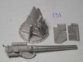
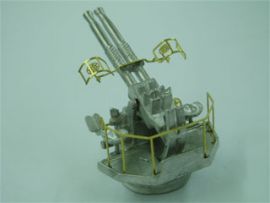
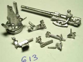
A 1/96 scale kit - click on the pictures above to see the construction series. (If you move your mouse to the left or right side, halfway up on each picture, you will be able to move on to the next picture in the series.)1) Complete list of kit parts2) Drill out rear platform 0.7mm drill and fit backframe [ use cyano glue ] look carefully to see where to bend frame. Back rail should be over triangular section on platform3) Fit circular base ring and platform to trunnion. Drill out trunnion holes for handles 0.45mm4) and 5) Fit twin chutes to trunnion base and platform triangular section6) Cut out PE sights and guards and split as shown7) Drill out barrel 0.45mm and fit PE sight8) Twist sight guard through 90 degrees9) Curve over the guard as shown10) Twist sight bar through 90 degrees11) Pull up target sight and rear eyepiece12) Drill out 4 cooling hose holes 0.7mm13) Fit elevation gear into breech channel . The gear sits up into the barrel middle gap.14) Fit barrel assembly between the trunnion ears and cyano, also where the barrel tails slot into the chutes.15) Fit seats as shown both sides16) Fold up and fit the PE elevation and training handles17), 18) and 19) Using 22g copper wire 22mm long curved as shown for each hose, fit the 4 cooling hoses.This completes the construction guide.
Construction notes:(Click on the thumbnail pictures above. Hover the mouse towards the top left or right of the picture when it opens, to move on to the next picture or back to the previous one.)1: There are 6 parts in the kit.2: Drill the baseframe 0.5mm drill to take seats and trunnion wire handles.3: Clean off the two front pads and rear pad of the baseframe to allow trunnion to sit squarely on the baseframe.4: Jiggle the baseframe over the trunnion and glue in position using the three pads.5: Fix the recoil cylinders to the barrel.6 and 7: Glue the barrel assembly into trunnion with tail in chute.8: Bend 28g of copper wire or similar (not provided) to this shape x2, for the handles.9: Fix the handles into the trunnion where shown.
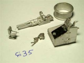
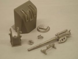
Construction guide:(Click on the thumbnail pictures above. Hover the mouse towards the top left or right of the picture when it opens, to move on to the next picture or back to the previous one.)Click through the images above to see how to assemble the Gun Kit. The pictures are as follows:1. The complete kit of parts2. Photo 2 shows the right hand trainer column attached3. Photo 3 shows the left hand elevation handwheel attached4. Photo 4 shows the fuse setter platform attached5. Photo 5 shows the two seats in position6. Photo 6 shows the mount with the barrel attached7. Photo 8 shows the gun site piece fitted to the barrel which finishes the assembly
1/192 scale photo-etch
1/200 scale Photo-etch
1/48 scale photo-etch
Atlantis
Cowl Vents
DVDs
General Merchant
Merchant Shipping
Royal Navy
Construction guide(Click on the thumbnail pictures above. Hover the mouse towards the top left or right of the picture when it opens, to move on to the next picture or back to the previous one.)1. Full kit of parts to clean up2. Fit top flange3. Fit 4 rows of bomblets4. Fit rear blast shield and drill out control colunm to fit wire handle as shown and then fit the control column into the shield hole and top flange hole, [wire not supplied].5. and 6. Completed kit.
This is a scale 1/96 part.Construction guide:(Click on the thumbnail pictures above. Hover the mouse towards the top left or right of the picture when it opens, to move on to the next picture or back to the previous one.)a) the complete kitb) fix the right-hand bracket where shownc) fix the searchlight bowl in the RH bracket hole and in the LH bracket open slotd) drill and fix the handwheel where shown and after inserting a clear disc [ not supplied ] fix the dome shaped rear piecee) the complete assembly
P1 twin bitt/bollard 44mm long x 11mm wide x 11mm high [1 in 48 scale]***This is an END OF LINE item – once these are gone, they are gone!**(The copyright of this item remains with John R Haynes.)
Construction Guide:Cut out the three openings in the shieldAssemble the gun with the w/m base (having a slight angle at the front edge) sliding into the trunnion.Drop the barrel into the top of the trunnion and fix and then fix the sight bar where shown. Lastly drill out the wheel sockets with 0.8mm approx drill and fix the two wheels.Slide the assembled gun into the shield between the trunnion bottom flange and the two angled side supports.
Please note: No shield is included with this kit.Construction Guide:
1. Solder/Glue these three sections together - make sure that you get the indicated FFF and RRR.2. Put on the 1and 14 end brackets.3. Start to fix all other internal brackets -make sure 2a slots into 2a position. Spring sides to help assembly.4. Fix 4 x S brackets where indicated.5. Bend up A and B brackets --take care when soldering top of brackets not to intefere with cetntral hole/slot with excess solder/glue.6. Fix A and B to main frame [ this is a tight fit ] and add the 4 multi-hole strip to the brackets to close the gaps.7. Bend up loose tray and fix where shown at the Front RH side. No location provided as this tray is optional.8. Bend up the two brackets that fit onto the underside of A and B brackets. These represent the wheels that travel around the edge of the circular raised central drum on which the toothed annular gear sits centrally.9. This is the start of the two loose/sliding extension pieces, fit one side onto the bottom piece.10. Fix all 5 internal spacers keeping the smallest tab at the bottom. This will allow the assembled piece to slide without fouling.11. Fix the top piece which sits below the top of the side pieces.12. Fix the remaining side to complete and clean up.13. This shows the sliding extension piece in position.14. Aircraft Trolley, fold up as shown.15. Add brackets Z and X.16. Fit to the Catapult the trolley where required with the higher trolley brackets to be secured to the Walrus aircraft [ JRH 603 ] towards the tail end and the lower brackets to be secured under the aircraft lower wing where the fuselage has a step.17. The ring provided sits centrally on the raised circular platform. For more information on this Catapult , obtain a copy of Model Shipwright number 33 dated Sept 1980 ISBN 0 85177 190 4 This article has pictures and lots of other ancilliary information.
This plan is to go with my 1/96 hull sold by Fleetscale.com and many fittings are in the shop.
Construction:a: Start of Assembly ------ Fit together the side framesto the base.b: Make sure to fit the pivot re-inforcing tabs when sliding the front panel back at an angle.c: Fold up the top tray and attach to crane base at the top of the left hand side.d: Fit the two top tray supporting brackets.e: Spring fit the two white-metal drums where shown and glue on the resin parts shown in the picture . To get good adhesion lightly run the brass with fine sandpaper before fixing.f: Another view of previous step.g: Fit the back panel. You will need to trim the locating tabs a little to get the back on.h: Fit the other base parts as shown.i: Fit the top tray with the textured floor.j: fit the top tray gear.k: Cut out the Jib parts and when assemblingfix the RH side piece to the top piece which is the shorter of the two [top and bottom].l: Remember that with PE the half-etched line is Bend to Close.m: Bend the bottom piece as shown.n: Drill all 5 pulley assembles [ 2 single/2 double and 1 four pulley ] with 1mm drill all the way through and the two double ones shown are fittedas shown.o: The central 4 pulley assembly must be fitted by drilling a new 1mm hole at the bottom of the side frame where shown and not at the existing hole.p: The final product.
Construction guide(Click on the thumbnail pictures above. Hover the mouse towards the top left or right of the picture when it opens, to move on to the next picture or back to the previous one.)1. The complete kit of parts.2. Drill out and bend wire as shown [ wire not supplied ]3. Fix this part where shown after drilling out the trunnion 4. Drill out and fix the elevating wheel andboth platforms5. Fix in place the sight assembly6. Fix on the barrel7. The completed gun RH8. The completed gun LH
Construction guide:(Click on the thumbnail pictures above. Hover the mouse towards the top left or right of the picture when it opens, to move on to the next picture or back to the previous one.)1: There are 6 parts in the kit.2: Drill the baseframe 0.5mm drill to take seats and trunnion wire handles.3: Clean off the two front pads and rear pad of the baseframe to allow trunnion to sit squarely on the baseframe.4: Jiggle the baseframe over the trunnion and glue in position using the three pads.5: Fix the recoil cylinders to the barrel.6 and 7: Glue the barrel assembly into trunnion with tail in chute.8: Bend 28g of copper wire or similar (not provided) to this shape x2, for the handles.9: Fix the handles into the trunnion where shown.
Turbinia
Uncategorized
US Navy
Construction guide(Click on the thumbnail pictures above. Hover the mouse towards the top left or right of the picture when it opens, to move on to the next picture or back to the previous one.)1. Full kit of parts to clean up2. Fit top flange3. Fit 4 rows of bomblets4. Fit rear blast shield and drill out control colunm to fit wire handle as shown and then fit the control column into the shield hole and top flange hole, [wire not supplied].5. and 6. Completed kit.
This is a scale 1/96 part.Construction advice:(Click on the thumbnail pictures above. Hover the mouse towards the top left or right of the picture when it opens, to move on to the next picture or back to the previous one.)a) Showing the 9 parts in the kit.b) Fit the circular base into the baseframe keeping the circular base bottom ring rear-facing.c) Note that the 2 mainstruts have a noticable bend to the bottom fixing ring. The top ring has a lesser angled bend.d) Drill the top wheel assembly 1mm and fix the rear shorter strut to this.e) Drill the baseframe 1mm to fix the two main long struts. The hole in the baseframe should be just above and to the rear of the rear pip.f) Fit all the struts and locate the two main strut loops onto the top wheel assembly pips.g) Fit the top plate to the baseframe.h) Fix the seperate wheel assembly to the top plate on the baseframe.i) Seperate wheel for the PE crane JRH 703.j) On completion, the Crane should look like this.
This is a scale 1/96 part.Construction advice:(Click on the thumbnail pictures above. Hover the mouse towards the top left or right of the picture when it opens, to move on to the next picture or back to the previous one.)a) Showing the 9 parts in the kit.b) Fit the circular base into the baseframe keeping the circular base bottom ring rear-facing.c) Note that the 2 mainstruts have a noticable bend to the bottom fixing ring. The top ring has a lesser angled bend.d) Drill the top wheel assembly 1mm and fix the rear shorter strut to this.e) Drill the baseframe 1mm to fix the two main long struts. The hole in the baseframe should be just above and to the rear of the rear pip.f) Fit all the struts and locate the two main strut loops onto the top wheel assembly pips.g) Fit the top plate to the baseframe.h) Fix the seperate wheel assembly to the top plate on the baseframe.i) Seperate wheel for the PE crane JRH 703.j) On completion, the Crane should look like this.
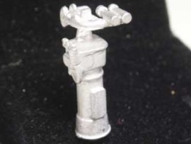
Construction Guide:This is JRH 93 the USN 5"/38 gun assembly guide.(Click on the thumbnail pictures above. Hover the mouse towards the top left or right of the picture when it opens, to move on to the next picture or back to the previous one.)1. All the parts in the kit.2. Fit the base ring to the base and drill out all the holes indicated for the control and fuse setting parts with a 1.4mm drill, but not the central trunnion fixing holes.3. Drill out the trunnion fixing holes with a 1mm drill and the barrel pivot holes with a 2mm drill. Cut approx 1/16"off the end of the LH trunnion [when sitting on the gun] forward projecting elevation gear quadrant to enable the forward control column to fit. Whilst fitting the two trunnion pieces, also fit the resin barrel after shortening the pivot stubs. Dry-fit to ensure that the barrel points exactly forward and both trunnions are upright. This may take several adjustments to get right4. Drill out the LH seat with a 1.4mm drill and fit to fuse setter block angled rod. Take the seat with the conical base and after drilling out the RH control column 1.4mm where shown, fit this seat.5. Fit the forward control column as shown. This must not interfere with the elevating quadrant - see 3.6. Fit the LH fuse setter block as shown.7. Fit the RH control column where shown.8/9. The finished gun. A rear safety rail can be fitted but this is not supplied.
A 1/96 scale kit - click on the pictures above to see the construction series. (If you move your mouse to the left or right side, halfway up on each picture, you will be able to move on to the next picture in the series.)1) Complete list of kit parts2) Drill out rear platform 0.7mm drill and fit backframe [ use cyano glue ] look carefully to see where to bend frame. Back rail should be over triangular section on platform3) Fit circular base ring and platform to trunnion. Drill out trunnion holes for handles 0.45mm4) and 5) Fit twin chutes to trunnion base and platform triangular section6) Cut out PE sights and guards and split as shown7) Drill out barrel 0.45mm and fit PE sight8) Twist sight guard through 90 degrees9) Curve over the guard as shown10) Twist sight bar through 90 degrees11) Pull up target sight and rear eyepiece12) Drill out 4 cooling hose holes 0.7mm13) Fit elevation gear into breech channel . The gear sits up into the barrel middle gap.14) Fit barrel assembly between the trunnion ears and cyano, also where the barrel tails slot into the chutes.15) Fit seats as shown both sides16) Fold up and fit the PE elevation and training handles17), 18) and 19) Using 22g copper wire 22mm long curved as shown for each hose, fit the 4 cooling hoses.This completes the construction guide.
Construction notes:(Click on the thumbnail pictures above. Hover the mouse towards the top left or right of the picture when it opens, to move on to the next picture or back to the previous one.)1: There are 6 parts in the kit.2: Drill the baseframe 0.5mm drill to take seats and trunnion wire handles.3: Clean off the two front pads and rear pad of the baseframe to allow trunnion to sit squarely on the baseframe.4: Jiggle the baseframe over the trunnion and glue in position using the three pads.5: Fix the recoil cylinders to the barrel.6 and 7: Glue the barrel assembly into trunnion with tail in chute.8: Bend 28g of copper wire or similar (not provided) to this shape x2, for the handles.9: Fix the handles into the trunnion where shown.
Construction guide:(Click on the thumbnail pictures above. Hover the mouse towards the top left or right of the picture when it opens, to move on to the next picture or back to the previous one.)Click through the images above to see how to assemble the Gun Kit. The pictures are as follows:1. The complete kit of parts2. Photo 2 shows the right hand trainer column attached3. Photo 3 shows the left hand elevation handwheel attached4. Photo 4 shows the fuse setter platform attached5. Photo 5 shows the two seats in position6. Photo 6 shows the mount with the barrel attached7. Photo 8 shows the gun site piece fitted to the barrel which finishes the assembly